


 Mail To Creater.
The Laboratory of Engineered Timber Joints (ETJ) was started in October in 1988 when the Forestry and Forest Products Research Institute (FFPRI) was largely re-organized. The origin of ETJ was the Laboratory of Newer Function Development where the timber joints were researched before then. The research range of ETJ is everything which wedding timber mechanically and also relates joints and connections in timber construction. We are mainly researching on joints of heavy timber structure and its structural performance. These descriptions are brief introduction of recent researches done mainly by the member of ETJ At the end of this booklet, some miscellaneous researches are introduced.
Laboratory of Engineered Timber Joints
Timber Engineering Section, Wood Technology Division
Forestry and Forest Products Research Institute (FFPRI)
Forestry Agency
Ministry of Agriculture, Forestry and Fisheries (MAFF)
PO Box 16, Tsukuba Norin, Ibaraki, JAPAN 305
Phone: +81-298-73-3211 ex. 585	facsimile: +81-298-73-3798
We survey the mechanical properties and characteristics of basic unit of the fastened timber joint within the wooden structures. And these results are used for structural timber joint design as fundamental property resources.
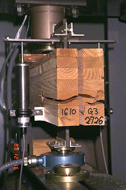
We summarize the results of creep test with Douglas-fir. We had pay attention not only usual maximum stress and primary stiffness, but also deformation of maximum stress, maximum embedding deformation, the stress of then and integral of stress deformation relation. The load angle to grains, cleavage length of grains and thickness are applied as parameter. Results are compared with Hankinson-formula.
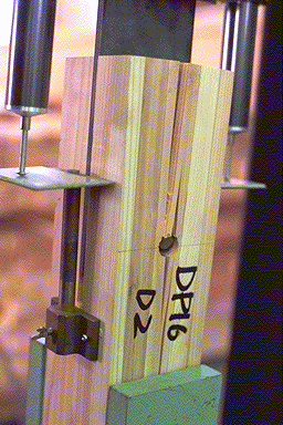
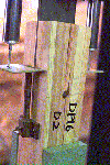
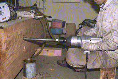
Tensile test of fundamental Drift-pin joint
Share & Cleavage test of Drift-pin joint
Creep loading test of Nailed joint
In structural design of wooden structure with axial members, the joints has been evaluated as pin joint which has only axial and sharing function of traveling forces except moment force. We innovate and develop its design as a joint which can transmit moment from one-member to the other member. This Joint design expand wooden frame probability and it is necessary to planning larger complicated wooden structures.
As if the safety factor was well expected, the structural design is more economic one when the steel splice plates were well evaluated for plastic material. In using these exceptions, we propose more economical design method for steel plate insert type drift-pin fastened joint. We also studied its accuracy with some experiments of full-sized specimen. We secured its extremely strong joint ability from its results lithe some restrictions : *Drift-pin length * 8d ~ 10d, *End distance * 7d, *Edge distance * 4d, fastener*s space * 7d, where `d` is diameter of drift-pin.
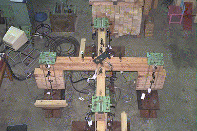
Cyclic loading of Moment-Resisting Full-sized T-shape specimen
Close up of Full-sized T-shape Joint
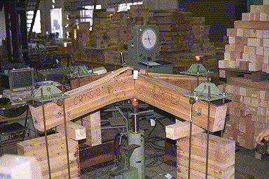
Cyclic loading of Moment-Resisting Full-sized portal frame
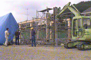
Field Loading of practical frame
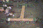
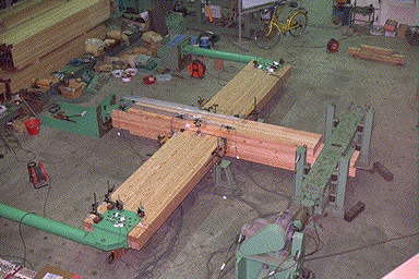
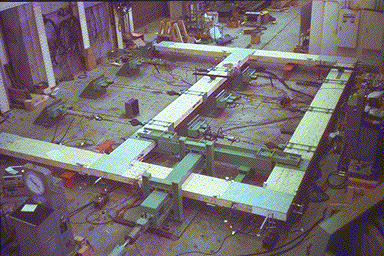
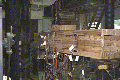
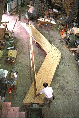
Plane lattice beam has many advantages because it can sustain less stress at each member than one-directional structures, and also high anti-buckling performance. In this study, we tested * Cross-shape* unit lattice beams by center point bending test until failure. Failure mode were very ductile and maximum strength was also higher than that expected from one-directional beam specimen.
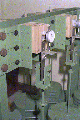
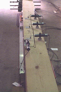
As mentioned before, *Cross-shape* lattice beam specimen showed firmly stable deformation until final collapse become no buckling occurred, contrary to this one-directional beam joint buckled early at steel splice plate. Dynamic test was done before destructive test was conducted. An impact hammer and acceleration pick-up devices were used to measure forced vibration mode (see photo.)
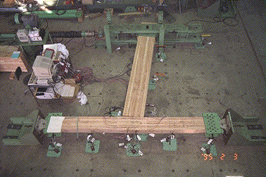
Bird eye view of Lattice Beam fundamental unit
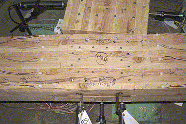
Loading test of lattice beam fundamental unit
Evaluation of dynamic damping on lattice beam
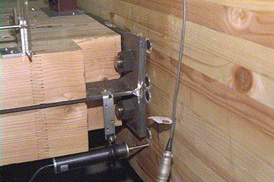
In addition to one-directional glulam semi-rigid portal frame, we extended our technique to *the two-way moment-resisting joint.* For this end, we developed new special connector to realize two-way joint. The photo shows how this newly developed connector *Lag-screw Bolt* is being derived into large glulam column with which two-way glulam semi-rigid portal frame structures can be constructed.
Recently, new demands for the moment-resisting joints usable to two-ways and multi-story glulam portal frames are increased. For this end, so-called conventional moment-resisting joints which can be used only to the one-way portal frame was modified in some points. Structural performance of the two-types moment-resisting joints , i.e., *Pre-driven Lag-screw method* and *Lag-screw Bolts method*, were examined by assuming that. These are used for a four-story two-ways glulam portal frame structure. Test results showed that *Pre-driven Lag-screw method* gave higher stiffness while *Lag-screw Bolts method* showed higher strength. Finally a semi-rigid frame analysis by F.E.M. showed that a four-story two-ways glulam portal frame structure can be built judging from the experimental results.
Driving Lag-screw Bolt
Cyclic loading of Beam to Column Full-sized specimen
Close up of beam joint
Japanese Traditional carpentry joints have been estimated in the aspect of esthetic, good on-site assembly performance and fire resistance. But, its mechanical performance have not been sufficiently studied scientifically. So precise structural design was difficult. In this research, we would like to re-view this traditional joint technique so as to design by using recent engineering knowledge.
In this research, we subscribe the tensile strength of the Japanese Traditional Designed Timber Joint using Glued Laminated Timber. The traditional joint designs which we had test were Okkake-daisen joint and Kanawa joint. We applied 4 different size ( Height :from 100 mm to 300 mm ) as specimen. Also the dimensions ( Wood plug, etc. ) was constant ( 15 mm ) as if the specimen size was varied. We conclude that the tensile strength of Traditional designed timber joint was depends on its cross-section. And also the fracture state was different.
Tensile test of Full-sized specimen
Measuring positions of deformation
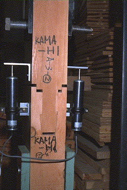
Tensile test of Pre-cut KAMA joint
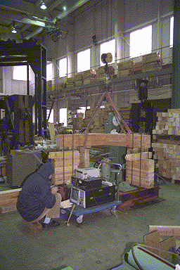
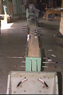
Cyclic loading test of Full-sized two-story portal frame
To make sure the possibility of rigid-jointed timber frame structures using straight glued laminated timber. Development of moment-resisting joints which enable to rigid jointed timber frame structures. Development of non-linear Finite Element Method which can consider the non-linearity of each fasteners composed of moment resisting joints. Verification of non-linear F.E.M. by the full-sized experiment.
Three types of moment-resisting joints were developed using the nailed joint with steel side plate, bolted joint with steel side plate and drift-pin joint with insert-type steel plate. Three full-sized( span :8m ) two story portal frames were made using three different joint methods. Comparison between non-linear F.E.M. analysis and full-sized loading test showed that the behavior of the portal frame composed of nailed joint was most precisely predicted, while drift-pin joint was affected by the initial clearance between pin-hole and pin.
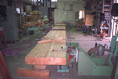
4 point bending test on Douglas-Fir glulam beam (Depth :91 cm)
Derivation of an equation for predicting modulous of rapture of glued laminated timber beam composed of arbitrary laminae without using size effect modification factor Verification of derived equation by a series of destructive tests on the full-sized glued laminated timber beams having various beam depth ( from 30 cm to 91 cm ) and span ( from 5.7 m to 12 m )
An equation which can predict modulous of rapture of any glulam beam composed of laminae with arbitrary grade, size and arrangement at the most critical section in the beam was derived by applying the multi-layer composite beam concept. Size effect on MOR could be expressed by only the equation derived in this study without using so-called modification factor. Experimental result obtained on the full-sized Douglas fir glulam beams was compared with predicted one based on the Montecarlo method. In consequent, derived equation was considered to be roughly held good.
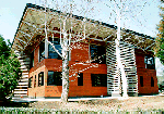
A few large scale G.L.T. buildings have been completed during past several years by utilizing joint research results which was partly contributed by ETJ. Below Photos show two representative large scale G.L.T. buildings which have deep relationship between us.
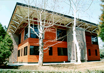
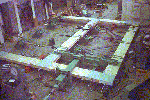
Forest Resource Analysis Division of FFPRI(Ibaraki, JAPAN)
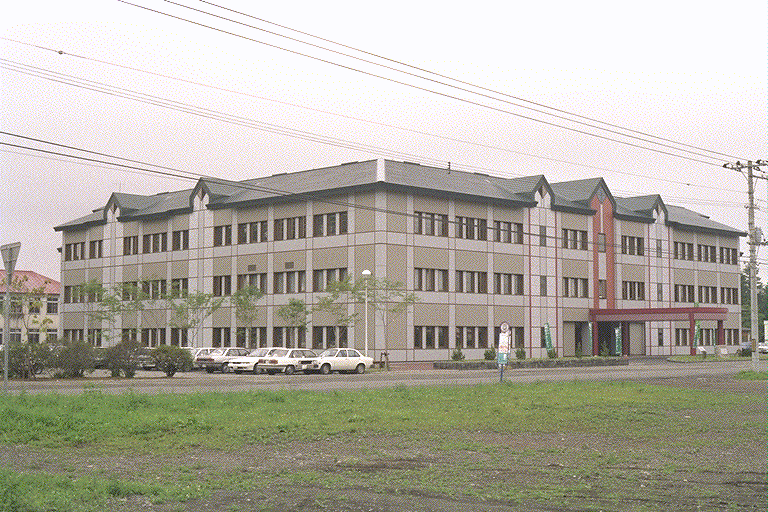
Obihiro brunch of Forestry Agency (Obihiro-c., Hokkaido, JAPAN)
In addition to wooden buildings, timber bridges have recently come back again as a new market of timber products here in Japan. In North America and Europe, there are a lot of timber bridge newly developed by the latest timber engineering knowledge. Even in Japan, a few researchers have just started their study in this field. ETJ members are also positive in this field and some actual timber bridge shave recently completed as shown in photos below.
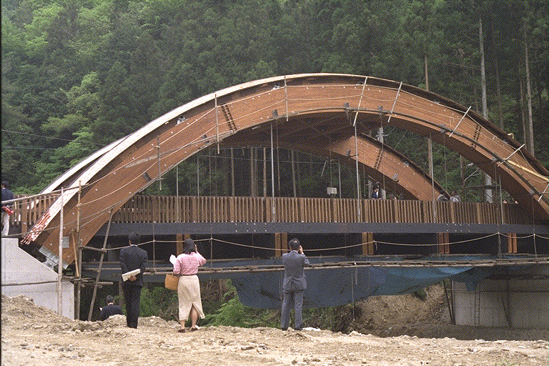
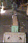
Wooden Arch Bridge made by Box G.L.T. Beam
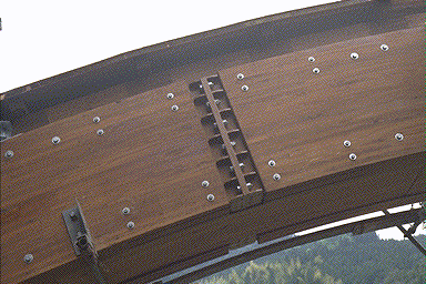
Close up of Box Arch Beam Joint
3 point bending test of Box G.L.T. Beam
Following is the list of researches done mainly by the members of the laboratory of ETJ except aforementioned research in this manuscript.
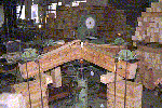
The Kobe earthquake gave us tremendous hazards for structural safety of existing wooden residential houses. ETJ members also attended for investigation of damaged wooden houses in Kobe and Awaji-island several times.

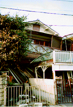
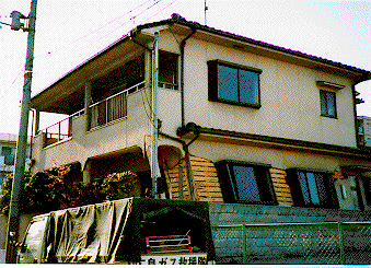
Destroyed House Buildings (Kobe-city, Hyogo, JAPAN)
Snap Shoot